Friday

SOA Governance Implementation Planning

As part of SOA Governance Solution using the Oracle Governance Suite of products, this is about planning the implementation of Oracle Enterprise Repository.

The Oracle Enterprise Repository is the key component of the Oracle's SOA Governance Suite. Implementing the Repository is the first step in the SOA Governance Solution.

• Define the SOA Governance model and Infrastructure, and review SOA Governance products as part of SOA Governance Solution including Oracle Enterprise Repository, Oracle Service Registry, and SOA Management Pack for Oracle Enterprise Manager, and Oracle Web Services Manager.

• Define Oracle Enterprise Repository (Implementation steps covering assets definition, adopting solution packs, defining stake holders, users and their roles, defining asset lifecycle including asset bootstrapping and asset harvesting.

• Conduct Repository usage sessions as part of user training focusing Users, Registrar and Administrator specific activities.
  • From Users view, look at how to submit an asset, search for an asset, and download and use an asset. View Projects to which the users are associated, asset subscriptions, and how users can submit asset reviews.
  • From Registrar view, look at how to review an asset, and how to approve or reject submitted asset.
  • From Administers view, how to create Roles and Users, how to assign Users to Roles, how to create Projects and customize the Repository for enterprise specific needs.
• Outline integrating Repository with Reporting Server (OBI Publisher), with Active Directory for User Authentication, with JDeveloper for design time integration, and with Service Registry for run time integration.

• Define Reporting requirements and its usage including developing Custom Reports.

Wednesday

OAuth Setting for Twitter OFM SOA Application

This is related to my previous article about sending tweets to twitter.com from Oracle Fusion SOA Web Service application. Refer http://sreenisetty.blogspot.com/2010/05/tweet-from-ofm-soa.html

The SOA Web Service application prototype I had built was using the basic authentication using user name and password while connecting to the twitter.com user account.

Effective August 2010, Twitter has disabled the applications posting tweets using basic authentication. Basic authentication was the simple approach for applications to connect to the Twitter User Accounts using just the user name and password. But may not be the smartest way to connect given the security and account maintenance challenges.

OAuth based authentication is the recommended approach. All of the applications using the basic authentication need to switch to OAuth authentication.

This write up is the record of the steps I followed to switch my Fusion SOA Web Service tweet application that was using basic authentication to OAuth based authentication.


Summary steps:
Step 1: Register the application that tweets using an API. This is to register the application as a authorized source of tweets related to the Twitter User Account.

Step 2: Obtain OAuth Access Token.

Step 3: Update the client application API to use the Access Token instead of the basic user name and password.

Following sections details about each of these steps.


Register the application for OAuth access and obtain the Consumer Key and Consumer Secret Key


Open the link in a browser: http://twitter.com/oauth_clients/new
Enter the application details to obtain OAuth specific access.


Twitter generates Consumer Key and Consumer Secret Key for the associated Twitter user account. The keys will be used to obtain Access Token in the next steps.


Obtain the Access Token for OAuth
 
It is a three level process.

1. Generate Authorization URL
2. Obtain PIN
3. Generate Access Token

The code to perform this one time setup is: OAuthSetup.java


The code output:
C:\>java OAuthSetup

Open the following URL and grant access to your account:
http://api.twitter.com/oauth/authorize?auth_token=Vy8qPu0hWf5iFK4q4yCuQBQpOd9Xpjgd8qj98saULP

Open the URL in the browser


Enter the twitter account user name and password and select ‘Allow’


Note the generated PIN


Enter the PIN at the prompt in the OAuthSetup.java program, and generate the Access Token.
 
Note down the Access Token and Access Security Token and save it safe. This will be used in the twitter client to authenticate.
 
Here is a sample twitter client usage in Java which uses OAuth with Consumer Key, Consumer Secret Key, Access Token and Access Security Token to authenticate with twitter.com.
 
TwitterFactory factory = new TwitterFactory();
AccessToken accessToken = new AccessToken("Access Token", "Access Security Token");
Twitter twitter = factory.getOAuthAuthorizedInstance("Consumer Key", "Consumer Secret Key", accessToken);

Thursday

Integrated SOA Gateway

Integrated SOA Gateway (ISG) is a SOA-based integration infrastructure for E-Business Suite R12 (EBS) with an objective to provide, consume and monitor web services for out of the box integrations in a heterogeneous ecosystem.

ISG is built on top of Oracle Fusion Middleware (OFM) and Service Oriented Architecture (SOA) and uses the Oracle Fusion Middleware Adapter for EBS available in OFM SOA Suite 10.1.3.x and 11g.

The components of ISG to achieve the above objective include:
Integration Repository
Integration Service Framework (ISF)
SOA Monitor


Integration Repository
Integration Repository is catalog of all EBS public integration points. Exposes the following integration types as web services:
• PL/SQL API
• Business Events
• XML Gateway
• E Commerce Gateway
• Open Interface Tables/Views
• Concurrent Programs
• Business Service Object
• Composite Services

Integration Repository provides easy steps to search and deploy an integration type as a web service.

For example,
1. Search the Integration Repository and identify the public PL/SQL API that needs to be exposed as a web service.
2. Generate a WSDL for it by pressing the Generate WSDL button and creating a Service.
3. Deploy the Service by pressing Deploy button.
4. Grant the permission controlling the access to this Service.
5. Any industry standard web service client will be able to invoke EBS PL/SQL API as a service.

Service Invocation Framework
The Service Invocation Framework of the Integrated SOA Gateway allows SOAP based web service invocation from an EBS instance

For example,
1. Create and deploy a BPEL process into SOA Suite middle tier (10g or 11g) and identify the BPEL process’s WSDL.
2. Create a Business Event in EBS
3. Create a Subscription of type “Invoke Web Service” and consume the BPEL process’s WSDL in the subscription.
4. The web service can be called passing the parameters, and receive the response parameters back into the calling process.
5. The BPEL process’s WSDL can be replaced with any standard web service’s SOAP WSDL.

SOA Monitor
SOA Monitor is a managing tool to monitor the SOAP request and response traffic with SOA and Web Service Provider.

For example, the Monitor allows to audit web service calls from outside world to the EBS instance where, suppose a PL/SQL API is exposed by the Integrated SOA Gateway. It also shows the actual response XML sent back from EBS to the caller.

Security
Web Services that are exposed within EBS are accessible to clients with two levels of access control: User Authentication and User Authorization.

The client is authenticated against the EBS instance based on the credentials they present as part of the WS-Security Headers.

The client’s authorization to invoke the service is validated within the SOA Gateway with the values Responsibility, Responsibility Application, Security Group, Organization ID, NLS Language, that are present in the SOAP Header of the client request.


Summary
The new Integrated SOA Gateway is a SOA based Enterprise Application Integration technology to integrate E-Business Suite instances with external systems over SOA based Web Service protocol.


References
ISG R12.1 Implementation Guide (E12169-03)
ISR R12.1 User Guide (E12064-03)

Wednesday

OFM Adapter for XML Gateway

Refer to the introduction to OFM Adapter for Oracle Applications from my previous post here

Oracle XML Gateway is a set of services that allows bidirectional integration with Oracle Applications using OAG standard XML messaging. Oracle Applications utilize the Oracle Workflow Business Event System to support event-based XML message creation and consumption.

For XML Gateway inbound message processing, the inbound message will be placed in the ECX_INBOUND queue by the Oracle BPEL process. Agent Listeners running on ECX_INBOUND would enable further processing by the Execution Engine. Oracle XML Gateway picks this XML message, does trading partner validation, and inserts data into Oracle Applications.

For XML Gateway outbound message processing, the outbound message will be first en-queued to the ECX_OUTBOUND queue. Oracle BPEL PM listens to ECX_OUTBOUND queue for the message with the same correlation Id BPEL. The message will then be de-queued to retrieve outbound data and then the outbound map will be invoked to update Oracle Applications.

The message will have XML payload of the transaction (PO, Invoice, etc) along with message attributes called XML Gateway Envelope.


Case Study 1 scenario – inserting a Purchase Order transaction into Oracle Applications through XML Gateway inbound message map PROCESS_PO_007 exposed as a Web Service.

The customer’s PO is input to the BPEL along with the ECX Header properties. The BPEL pushes this PO to ECX_INBOUND queue. Agent Listeners running on ECX_INBOUND would enable further processing by the Execution Engine. Oracle XML Gateway picks this XML message, does trading partner validation, and inserts order data to Order Management in Oracle Applications.

Pre-requisites:
Setup XML Gateway Header Properties
Setup XML Gateway Trading Partner
Activate ECX Inbound Agent and ECX Transaction Agent Listeners

Configuring the Adapter to enqueue:
1. Create a new SOA BPEL project (Composite with BPEL template) in a SOA application. Select the BPEL process as asynchronous and exposed as a SOAP service.
Application Name: XMLGatewayApplication
Type: SOA Application
Project Name: Inbound_PO
Technology: SOA
Composite Template: Composite with BPEL process
BPEL Process Name: EnqueuePO

2. Create a Partner Link service for Oracle Applications XML Gateway in the BPEL process by selecting partner link type “Oracle Applications” under BPEL Services.
Partner Link Service Name: XMLGateway_apps1

3. Configure the database connection to connect to the Oracle Applications’ database. Database Host Name, User Name, Password, database Port and SID fields are to be configured in the connection.

4. The adapter configuration wizard starts the Oracle Module Browser pulling interfaces data from Oracle Integration Repository that are supported by Oracle Applications Adapter and displays in tree structure.


5. Navigate to Order Management Suite > Order Management > Sales Order > XML Gateway > Inbound: Process Purchase Order XML Transaction (root element PROCESS_PO_007)

6. The wizard generates the WSDL file corresponding to the XML schema.

7. Configure the BPEL process to invoke XML Gateway by adding Invoke activity and wire to the Partner Link for XML Gateway. Select the ‘Enqueue’ operation.

8. Set the ECX Header Message Properties. The following property fields needs to be configured.
jca.apps.ecx.TransactionType: 'PO'
jca.apps.ecx.TransactionSubType: 'PROCESS'
jca.apps.ecx.PartySiteId: 'Site123'
jca.apps.ecx.MessageType: 'XML'
jca.apps.ecx.MessageStandard: 'OAG'
jca.apps.ecx.DocumentNumber: 'order_xml_01'

9. Map the XML PO payload from BPEL input variable to Partner Link’s Variables > Process > Variables > Invoke_Enqueue_InputVariables > PROCESS_PO_007

10. Deploy and test the BPEL process.


Case Study 2 scenario – responding a trading partner with Purchase Order acknowledgement transaction from Oracle Applications through XML Gateway outbound message map ECX_CBODO_OAG72_OUT_CONFIRM exposed as a Web Service.

When the PO is created and approved, a workflow creates the PO Acknowledgement flow and sends out the PO Acknowledgement XML file to ECX_OUTBOUND queue.

Pre-requisites:
Setup XML Gateway for correlation identifier labeling messages meant for specific agent.
Setup XML Gateway Trading Partner

Configuring the Adapter to dequeue:
1. Create a new SOA BPEL project (Composite with BPEL template) in a SOA application. Select the BPEL process as asynchronous and exposed as a SOAP service.
Application Name: XMLGatewayApplication
Type: SOA Application
Project Name: Outbound_POAck
Technology: SOA
Composite Template: Composite with BPEL process
BPEL Process Name: DequeuePOAck

2. Create a Partner Link service for Oracle Applications XML Gateway in the BPEL process by selecting partner link type “Oracle Applications” under BPEL Services and connect to the Oracle Applications.
Partner Link Service Name: XMLGateway_apps1

3. In the Oracle Module Browser, navigate to Other Interfaces > Custom Objects >XML Gateway Maps> Outbound > ECX_CBODO_OAG72_OUT_CONFIRM (root element CONFIRM_BOD_004)


4. The wizard generates the WSDL file corresponding to the XML schema.

5. Configure the BPEL process to receive from XML Gateway by adding Receive activity and wire to the Partner Link for XML Gateway. Select the ‘Dequeue’ operation.

6. Map the XML PO Acknowledgement payload from Variables > Process > Variables > Receive_Dequeue_InputVariables > CONFIRM_BOD_004 to BPEL response output variable.

7. Deploy and test the BPEL process.


Similar integrations can be built for interfacing with Oracle Applications using e-Commerce Gateway, PL/SQL, Concurrent Programs, Open Interfaces Tables and Views.


References
OFM Adapter for Oracle Applications 11g - User's Guide (E10537-01)

Sunday

Oracle Fusion Middleware Adapter for Oracle Applications

Oracle Fusion Middleware Adapter allows Oracle Applications Release 11i and Release 12 to connect to non-Oracle applications over Web Services integration deployed on Oracle Fusion Middleware SOA Suite 10g and 11g.

The Adapter supports various integration types PL/SQL APIs, Business Events, Open Interface Tables and Views, Concurrent Programs, XML Gateway Interfaces, and e-Commerce Gateway Interface. The Adapter leverages the Integration Repository to provide the source for the integration on the Oracle Applications. JDeveloper design time allows for browsing the Oracle Applications interface and configuring the adapter metadata. The interfaces within Oracle Applications are exposed as a Web Service by generating WSDL with J2CA extension.

Adapter connects to Oracle Applications through FND user name and password authentication. Oracle User Management function security feature is used for authorization to access and execute APIs that are exposed as Web services to update Oracle Applications. Application Context is used for secured transaction processing into and out of Oracle Applications.

Integration Design Time: The Oracle JDeveloper BPEL Designer is used to design BPEL-based process flows and Web services orchestration.

Designing the Adapter requires creation of a partner link in JDeveloper BPEL Designer starting the Adapter Configuration Wizard. The wizard allows selecting and configuring the Adapters for Oracle Applications. With proper database and service connection setups, select an interface in or out from Oracle Applications and add the XML schema. When configuration is complete, the wizard generates a WSDL file corresponding to the XML schema for the partner link. Additional process activities are added to the BPEL process orchestration.

Integration Run Time: The WSIF Provider converts the Web service invocation from BPEL PM Invoke activity to an outbound interaction call, and performs the reverse conversion in the other direction as a Web service response for a synchronous request-response message pattern. The WSIF Provider also supports the one-way asynchronous outbound interaction invocation such as integration with XML Gateway outbound message maps and outbound Business Events.


Next: OFM Adapter for XML Gateway integration type…

Saturday

Tweeting from OFM SOA!

After getting a Twitter Account and following a couple of Tweeters, it struck to me that I can use this simple yet efficient technology to make my work life easier.

On a day to day basis, over 1000 email notifications from various integration projects arrive to the mail box, out of which 10% of the notifications are significant; for example, notification that the critical bank feed went fine, the long running nightly scheduled job succeeded, etc,. To pull out the important ones on the go, on a smart phone, is tedious.

Traditional method: All the notifications are emailed to the mail box, without any priority.

Tweeting method: The significant notifications are tweeted to your smart phone, where as the others (along with the tweeted ones) are still emailed to the mail box.

A tweet of the notification will contain only the important data and the same notification is mailed with all the details. This way the important message is delivered fast and available for quick view and its details available in the mail (just like in the traditional method).

With all the technology, it is as secure as it can get. The tweets are sent out only to the followers, who are monitored by the tweeter. The tweeter permits as to who can be the followers.

Implementing Tweet as a Web Service

Java API for tweeting provides methods to publish tweets to the twitter account. Twitter4J is one such API. The Java API can be encapsulated in BPEL and deployed as a Web Service on Oracle Fusion Middleware SOA Suite. The Web Service would be deployed as a common service and invoked by other orchestrations to send tweets.

Architecture view


A common Twitter account is created for the group. In this prototype the account name is “ofm2tweeter”. Users with their own Twitter accounts become ‘followers’ of this account and view the tweets.

Security of the account and the tweets is important since the account will be on the internet domain. The account is restricted so that its visibility in the internet is restricted. The users ‘follow’ requests are verified by the Twitter account admin before allowing them to follow the account. Even the tweets are invisible to the public except for the approved followers

The Tweet Web Service
The Tweet Web Service “Tweet_BPEL_WS_V1” is built as an asynchronous BPEL service, and invoked by other orchestrating services. The service receives the message to be tweeted from the invoking services. It uses the twitter4j factory classes to make a connection to the twitter account and posts the tweets. The service responds back with the status of the tweet.

Here is a view of the BPEL implementation.


The users who follow the Twitter account get the tweets on their smart-phones or on their web accounts. Here is view of trial tweets viewed on Twitterrific application on iPhone.


Summary
Twitter makes following the notifications easier. An organizations’ biggest concern is information security, which is taken care by account settings, monitoring and administering the followers by the Twitter account administrator.

Tweeting is cool!

Tuesday

Master Cloud Operative!

CLOUD COMPUTING! Why is it everyone is talking about it all of a sudden. For a feature/technology that has been in use since the sixties, we hear about it so loud and clear for the first time.

With the publicity and popularity given to it by Oracle, a layman is hearing about it and comprehending with the term Cloud Computing.

Cloud computing is the delivery of software and hardware as services via the internet. It has evolved through a number of phases which include grid and utility computing, application service provider (ASP), and software as a service (SaaS).

But the concept of delivering computing resources through a global network is rooted in the sixties. However it has reached masses only in the recent years since the revolution in the internet bandwidth and the recent evolution of Web 2.0.

Looking back at the major milestones…
· Salesforce.com (1999) – that pioneered the delivery of enterprise applications through a web.
· Amazon Web Services (2002) – that provided cloud based computation services and storage.
· Amazon Elastic Compute Cloud - EC2 (2006) – that allowed business to rent computers and run their own computer applications.
· IBM Cloud Box (2008) - custom built, Linux based rack servers for Web 2.0 and cloud computing companies
· Google Apps (2009) – that offered browser based enterprise applications.
· Microsoft Azure - cloud platform taking one step further into cloud operating system called Windows Azure
· and many other...


Oracle has done it in the biggest possible way, taking it further as - software as a service, platform as a service, infrastructure as a service.

Oracle has addressed the major concerns of cloud computing – the security and the managing of cloud services, through its Identity Management and Enterprise Manager.

Follow the Oracle sponsored Stark Expo 2010, the Stark Industries international technology exhibition that runs on Oracle Cloud Computing.


Links:
http://www.oracle.com/us/technologies/cloud/index.html
http://ironman.oracle.edgesuite.net/ironman2/index.html
http://www.starkexpo2010.com/

Sunday

TOGAF and SOA

During my Oracle SOA and TOGAF certification, I had questions as to how SOA fits in the EA, and how TOGAF for EA support adopting SOA.

Here is an attempt to address that.

TOGAF, The Open Group’s Architecture Framework, is a generic Enterprise Architecture framework. It provides enterprises with a 4 dimensional model- Business, Information, Application and Technology Architecture that enables to design, evaluate and build the right architecture for any organization ensuring Business-IT alignment at the enterprise level.

SOA, Service Oriented Architecture, is an industry standard architectural style that re-structures applications as loosely coupled, modular services to deliver boundary less information flow. It bridges the gap between Business and IT through well defined, Business-IT-aligned “Services”.

The objectives of TOGAF and SOA are quite similar. However TOGAF is an architecture framework and SOA is an architectural strategy.

How do the principles of service orientation apply to the enterprise architecture? To answer, let’s take each phase of TOGAF’ ADM, Architecture Development Method, and see how TOGAF enables to do SOA.

TOGAF ADM phases cycle through A to H for incremental architecture development. Phases A to F for each cycle is carried out in parallel to phase G the implementation governance phase for the previous cycle. Phase 0 – the preliminary phase is for each cycle start.

Phase 0: Framework and Principles
This is the preliminary phase where the architecture footprint for the organization is defined. And the approach to do the architecture is laid out by selecting the framework and the guiding principles.

This is the starting point for adopting the TOGAF ADM framework, and adopting SOA and service orientation as architecture principles.

An example architecture principle for service orientation is that the architecture is based on a design of services which mirror real-world business activities comprising the enterprise business processes.


Phase A: Architecture vision
The Architecture Vision phase is concerned with defining scope for the architecture project, creating vision and obtaining approvals from stakeholders to proceed.

High-level description of the final architecture that is envisioned is produced. The SOA vision in the architecture is defined highlighting the type of services, its composition and contract, how they support the business processes and its business benefits.

An example, a particular segment where SOA should be used, and call for use of web services for interaction between segments.


Phase B: Business Architecture
The Business Architecture phase aligns the enterprise’s business processes, people, operations and projects with its overall strategy. Provides the foundation to build Information Systems Architecture and Technology Architecture.

Business functions, requirements and processes are analyzed. The information that is central to the business operations which is crucial for SOA is described identifying and defining the portfolio services.

Models are developed describing the SOA solution architecture:

• Business Process Model – set of diagrams that show the business processes and their decomposition, their interactions, and the information with which they are concerned.

• Business Roles Catalog – list of human and organizations users of the system.

• Business Vocabulary – list of key terms used in describing the business processes.

• Business Rules Catalog – list of business rules and its description.

• Business Services Catalog – list of business services showing their providers, their potential consumers, and the service contracts.

The models provide a view to demonstrate to stakeholders how SOA specific concerns relating to Business Architecture are addressed.


Phase C: Information Systems Architecture
The Information Systems Architecture phase defines the types and sources of data necessary to support the business, and define the kinds of application systems necessary to process the data.

The Data Architecture includes the development of:
• Business Data Models
• Logical Data Models
• Data Management Process Models
• Data Interoperability Requirements (example, XML schema, security policies, etc)
• Data Architecture Building Blocks

The application architecture for SOA means groups of loosely-coupled services, the definition of these services and the interaction between them based on the previously defined data models.

An example, in services that exchange XML messages, the message schema and tags should be based on the information and data models.

With SOA, the traditional software applications are replaced with interoperable services. However, existing applications, and any new traditional type applications that might be added, are also listed in the application portfolio. Services are identified that cover the application functionality.

The Application Architecture includes:
• Service Interaction Model – set of diagrams that show portfolio services, interaction between them and their use of data.

• Business Process/Service Matrix – shows which service caters to which business processes.

• Service Consumer Matrix – shows which human and external systems consume which service.

• Service Contract and Policy Catalog – catalog of service contracts, and policies for each service contracts.

• Service Access Control Model – set of diagrams that show how access to services is controlled.

• Service Configuration and Provisioning Model – shows how services are configured and provisioned with resources.

• Service Loading Model – shows expected load on the services, time patterns of service use, and performance requirements.

The models provide a view to demonstrate to stakeholders how SOA specific concerns relating to Application Architecture are addressed.


Phase D: Technology Architecture
The Technology Architecture phase maps the application components deified in the Application Architecture phase into set of software and hardware technology components, defining the software and hardware infrastructure needs to support the portfolio services.

For SOA the infrastructure building blocks include:
Activity Monitor – is a program that interfaces with messaging programs and monitors the messaging activity and results. Example: Business Activity Monitor (BAM) in the Oracle Fusion Middleware Suite.

Composition Engine – is a program that executes scripts that control services and describe interactions between them. It is used to perform one or more of the services in a composition. Example: Business Process Executing Language (BPEL) Process Manager in the Oracle Fusion Middleware Suite.

Data Translator – is a program that converts data from one representation to another. Example: Extensible Stylesheet Language Transformations (XSLT)

Data Security – services to ensure message integrity and confidentiality. Example: WS-Security

Service Bus - standards-based integration platform that combines messaging, web services, data transformation, and intelligent routing between services. Example: Enterprise Service Bus (ESB) in the Oracle Fusion Middleware Suite.

Service Registry – enables discovery of services. Example: Oracle Service Registry that is based on the standard Universal Description Discovery and Integration (UDDI).

Service Repository – enables hosting of metadata for the services, code versions, documentation. Example: Oracle Enterprise Repository.


The Technology Architecture for enterprise SOA includes:
• Technology Portfolio – catalog of SOA run-time infrastructure, SOA development environment, service components technology, and service interface technology.

• Service/Physical System Matrix – shows which physical systems host the services.

• Service/Technology Matrix – shows which items in the technology portfolio are used in the performance of which services.


The models provide a view to demonstrate to stakeholders how SOA specific concerns relating to Technology Architecture are addressed.


Phase E: Opportunities and Solutions
The Opportunities and Solutions phase looks at the implementation options identified in target architecture (example build vs. buy vs. re-use options), and verify check point suitability of implementation.

Existing services and solution portfolios in the enterprise are viewed before making a decision on whether to develop the services in-house, or use the services provider by external companies, or acquire software products that perform the services. Whether or not existing systems should be replaced all at once, and options looked at so that the new and old systems can coexist.


Phase F: Migration Planning
The Migration Planning phase is about prioritizing, selecting major work packages, and developing the plan for the architecture implementation. The cost, benefits, dependencies, and priorities are assessed and a detailed implementation plan is produced that guides the next phase.


Phase G: Implementation Governance
The Implementation Governance phase provides architectural oversight of the implementation, to improve the quality of the implementations in general and in particular to ensure conformance with the architecture.

SOA Governance is viewed as the application of corporate governance, information technology (IT) governance, and enterprise architecture (EA) governance to SOA. SOA Governance extends IT and EA governance, ensuring that the benefits of SOA are realized. This means governing, not only the execution aspects of SOA, but also the strategic planning activities.


Phase H: Architecture Change Management
The Architecture Change Management phase establishes procedures for managing changes to the new architecture.

Where SOA has not previously been used within an enterprise, this phase is an opportunity to assess and consider adopting the principles of service orientation.


Putting it all together… Using TOGAF for end-to-end SOA
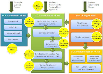


Summary
Effective enterprise architecture covering business operations, people and technology is critical to business survival and success. Focusing on the Business and IT, the quality of an enterprise's IT architecture has a direct impact on its business performance. This is where the principles of service orientation fit in benefitting the IT architecture.

Following TOGAF ADM, a set of key business requirements are identified in phase A, the business requirements are further defined in phase B, information systems requirements are identified in phase C, software and hardware infrastructure is identified in phase D. Planning and managing implementation and changes are dealt in phases E through H.

With SOA, the IT systems perform services that are defined and described in the context of the enterprise’s business activities. Each service is identified, and what it does is clearly set out in the form of a contract. This principle enables use of techniques such as service composition, discovery, message-based communication, and model-driven implementation, which give fast development of effective and flexible solutions.

TOGAF’s ADM helps to establish clear links between business and IT objects in the enterprise architecture. SOA brings agility and interoperability to the IT systems in the enterprise architecture.


Keywords
SOA – Service Oriented Architecture
EA – Enterprise Architecture
TOGAF – The Open Groups’ Architecture Framework
ADM – Architecture Development Method


References
http://www.opengroup.org/togaf/
http://www.oracle.com/technology/tech/soa/

Wednesday

Integrating Legacy Applications with Oracle Applications via Oracle Fusion Middleware

I have been managing an integration requirement to automate the transactions sync between Oracle Applications E Business Suite MFG module and legacy mainframe application.

The solution is built on Oracle Fusion Middleware (OFM) SOA Suite (BPEL and Web Services), to interface between the Oracle Applications E Business Suite (Oracle Apps) and the legacy application.

Manufacturing related transactions - Item Master, Shipment, Purchase Order, Shop Order, Cost, and Internal Sales Order are created out of Oracle Apps into FTP site associated with the Oracle Apps. OFM sweeps them moving to legacy FTP sites. Programs on the mainframe load them into legacy application.

Internal Sales Order, PO Receipt, Safety Stock, Sales Order, Shop Order, and Inventory are synced from legacy applications to Oracle Apps. For this, first the files are moved from legacy FTP to the FTP site associated with Oracle Apps. Next the files are loaded into Oracle Apps using the standard EBiz APIs via Concurrent Requests.

Oracle Fusion Middleware Adapter for Oracle Apps provides the following interface types:
1. XML Gateway
2. e-Commerce Gateway
3. Business Events
4. Concurrent Programs
5. Interface Tables and Views
6. PL/SQL API

More about each of these interface types for another time...


In the current solution approach, combinations of option 4 and 6 concepts are used.
1. A PL/SQL script (Stored Procedure) acts as an abstraction layer between OFM and Oracle Apps.
2. The PL/SQL determines which concurrent request to submit within Oracle Apps based on the transaction specific file name that OFM provides as a input parameter.
3. The PL/SQL returns the status of the concurrent program execution along with the ‘request id’ as a return parameter.

Internally within OFM, the Stored Procedure invocation is encompassed into a Web Service. A WSDL is generated within BPEL Process Manager for the Stored Procedure. So whenever a particular transaction is synced from legacy to Oracle Apps, the Web Service is invoked within OFM passing the file name as a parameter. This Web Service invocation is in synchronous mode. The resulting ‘request id’ is communicated to system users via OFM as an email notification.

With this approach, the concurrent program details for each of the listed transactions and the required user responsibility are abstracted to the OFM. OFM uses just a database user account. Any changes in the concurrent programs, or its parameters, etc., does not warrant a change in the OFM, rather are isolated within the PL/SQL.

Hands on with BIT EME-CE’s Managed File Transfer

Installation was quick and easy. Following the BIT’s Quick Start guide, downloaded the zip file bit-eme-ce-1.0.2.zip. Unzipping the file created two folders, each for EME-CE and Protocol Proxy.

My installation structure:
C:\ bit-eme-ce-1.0.2\ eme-ce-1.0.2
C:\ bit-eme-ce-1.0.2\ protocol-proxy-ce-1.0.2

Pre-requisite for EME is JDK 1.5+. When EME starts, it refers to the environment variable JAVA_HOME. JAVA_HOME should point to a valid installed JDK root folder.

Started the Protocol Proxy service first through the start script C:\bit-eme-ce-1.0.2\protocol-proxy-ce-1.0.2\bin\startup.bat.

Next, started the EME service through the start script C:\bit-eme-ce-1.0.2\eme-ce-1.0.2\eme.bat. This is a wrapper to start the Mule.

Protocol Proxy starts the Tomcat web server and FTP server. EME starts the Mule ESB Server, Derby Database on port 1528, Jetty Web Server on port 8888 and ActiveMQ JMS Server.

EME connects to Protocol Proxy during its start up to load the MFT agents. It throws exceptions if it cannot connect to Protocol Proxy.

EME provides browser based interfaces for administration, configuring trading partners, translations, and viewing messages, etc.

The below lists the URLs hosted on the localhost with default ports:

Admin login to EME:
URL:
http://localhost:8888/
Login name: admin
Password: password

EME Admin console has features to:
View the status of the Derby, Jetty and JMS services that were started along with EME
View the messages that were transacted with the Trading Partners
View the event log to monitor the errors
To create and manage Trading Partners, setting the profiles and XSLT based message translations
Create Users for EME and manage the ACL for Users

Admin interface to Protocol Proxy:
URL:
http://localhost:80/proxy-admin
Login name: eme
Password: password

Protocol Proxy Admin console has features to create Trading Partner users for mainly for testing purposes, limiting to dropping files off and picking files up from Protocol Proxy, without actually being allowed into the enterprise/into firewall, where EME runs.

Trading Partner interface to Protocol Proxy:
URL:
http://localhost:80/proxy-portal
Login Name:
Password:

Trading Partner console allows the Trading Partners to send or receive transactions via files with EME either in Binary or ASCII format.

Trading Partners can transact with EME either via the Trading Partner interface to Protocol Proxy over HTTP or over FTP.

When a new Trading Partner is created in EME, a set of folders are created as part of Managed File Transfer feature. By default, EME polls the Proxy for new messages from Trading Partners for every 60 seconds. EME CE reads files from and writes files to directories in the default setup for Managed File Transfer.

{BIT_EME_CE_HOME}/eme-ce-{version}/MFT//in
{BIT_EME_CE_HOME}/eme-ce-{version}/MFT//out

After the start-up, logged into EME Admin console and created a new Trading Partner by the name TP1. Enabled the flag that links the integration for this trading partner between EME and Protocol Proxy.


Logged into Trading Partner Console as TP1. Uploaded a test file with the file name “from_tp1_to_eme.txt” using the Upload.


EME in its schedule poll from Proxy retrieved the file from TP1 and moved it to MFT folder under C:\ bit-eme-ce-1.0.2\ eme-ce-1.0.2\MFT\TP1\in. The file was also listed in the EME Admin console under Messages tab with a link to download.

Next, logged into Protocol Proxy Admin console, and uploaded a file to TP1.


EME transmitted the file “from_eme_to_tp1.txt” to TP1. The file from EME was visible on the Proxy Portal for TP1 to view and retrieve, as well as on the FTP.


Observations:

1. EME has a lot of potential. With its Managed File Transfer, support for various protocols, message translation capabilities the possibilities are endless.

2. The HTTP(S) wrapper to the trading partners to do the standard FTP operations of file upload and download worked right out of the box. Managed File Transfer allows monitoring and controlling of messages in one place. The Message Viewer with its filtering options has potential to view historical transactions and its status. I have not yet explored further to understand the options for purging old messages along with its tranactional data.

3. Tested uploading files with varying sizes through the Proxy Portal using the TP login, starting with few kilo bytes and up to 2 mega bytes and these got transferred to EME flawlessly. However it failed to move a file with 3 MB with an exception at Mule level while reading the file from the trading partner. This test was run on Intel Duo 2.53Ghz with 4 GB RAM on Windows XP.

4. On the Proxy Portal for a TP User, the link “Outbox” lists the messages received from EME, and the link “Inbox” lists the messages sent to EME. The names seem to have interchanged. Inbox from TP perspective should relate to messages arriving to TP. Outbox for messages sent by TP.

5. EME Admin console and Proxy Portal UI is fairly simple and basic.

6. It would be helpful if the audit messages displayed in EME Admin console can be customizable. The search feature to list messages in the EME Admin console between the date ranges did not return correct values.

7. The Trading Partner or User management is limited. There is no option to delete trading partners or users. The available option is to turn off the ‘enabled’ flag.
I have not yet tested the message translation or Protocol Proxy deployment on HTTPS. There is a support for XSLT based translations. As well as supports HTTPS by means of configuring Tomcat for SSL. However, the current version does not provide secure FTP.


Response from BIT mentioned that they have recently tested the newest version and successfully transmitted files up to 1+ gigabytes. The newer version would also provide interface to customize audit messages to track the activities in the EME Admin console, and other enhancements. The 'Outbox' and 'Inbox' labels in Proxy Protocol is something customizable when implemented in a organization.

The new release version 1.1 is scheduled for the first of week of May 2010. Will have to wait for it to try it out...

Monday

EME by BIT

I am evaluating a product of Business Integration Technology (BIT) (http://businessintegrationtechnology.com), a business-to-business integration suite called Enterprise Messaging Engine (EME).

My initial intent is to understand the BIT EME solution and use as a benchmark versus what we are doing with Oracle Fusion Middleware. Look at the Open Source offering to see how it can complement Oracle Fusion Middleware or supplement in certain areas. The managed file transfer (MFT), a solution of EME that is something we don’t have now and will be looking closer at this component.

A brief on BIT EME:

EME is BIT’s open source based product powered by Mule (from MuleSoft) the open source enterprise service bus. There are two variations: EME Enterprise Edition which is fully supported complete solution, and EME Community Edition which is a complementary offering of Enterprise Edition for architects to evaluate. Current EME-CE version available is 1.0.2

The EME includes these additional features:
Protocol Proxy for a secure Internet point-of-presence, fully integrated with EME and Mule.
Managed File Transfer solution based on Mule/EME and Protocol Proxy.
Message Viewer for visibility to all enterprise messaging.
Business Documents Processor (BDP) to extend messaging to business users.

The architecture of BIT EME-CE:


EME is built on Mule open-source ESB providing integration framework. It leverages Apache Derby Database, Jetty Web Server, and ActiveMQ JMS Server.

Apache Derby is a Java based open source light weight database, Jetty Web Server is Apache's Java based open source HTTP and Servlet container, ActiveMQ JMS Server is Apache's Java based open source JMS server.

Protocol Proxy is a lightweight Apache Tomcat web server to provide the standard protocol services (FTP, SFTP, HTTP, HTTPS). It is deployable in the DMZ, securing the connectivity from external trading partners. The Protocol Proxy runs Web and FTP servers. By default web runs on port 80. It can be SSL enabled by configuring SSL for Tomcat. FTP runs on default port 21.


Next: Hands on with BIT EME-CE’s Managed File Transfer Service...

Thursday